adafruit backpack github

This is a Lithium Ion and Lithium Polymer battery charger based on the MCP73833. It uses a USB mini-B for connection to any computer or 'USB wall adapter'. Charging is performed in three stages: first a preconditioning charge, then a constant-current fast charge and finally a constant-voltage trickle charge to keep the battery topped-up. The fast-charge current is 500mA by default, but is easily adjustable from 100mA up to 1000mA by soldering a through-hole resistor on-board.This board is great for DIY projects because it has 3 indicator LEDs - one for power, one for charging status and a third that indicates when charging is complete. Keep the battery connected to the charger and pass power through the additional JST connector using the included cable!For use with Adafruit Lipoly batteries only! Other batteries may have different voltage, chemistry, polarity or pinout. Comes assembled and tested, includes a JST cable!5V input via mini-B USB connectorFor charging single Lithium Ion/Lithium Polymer 3.7/4.2v batteries (not for older 3.6/4.1v cells)500mA charge current, adjustable from 100mA to 1000mA by soldering in a resistorSeparate JST connectors for battery and load system so batteries don't have to be removed for chargingChip supports a 10K NTC thermistor which we have stuffed as a plain 10K.

For people who require temperature monitors (using high charge rates), remove the 10K and solder in the thermistor in its place0.1" (2.54mm) breakouts for the battery, DC, and status LEDsFree 2-pin JST cable included!Batteries and USB cable not included.It's been a busy winter (darn pesky day job) so I'm only now finishing up my hive temperature and humidity monitor. Here are a few build details and results.The key is the simplicity of the DHT22 temperature and humidity sensor coupled with an Arduino Uno R3 and the great DHT libraries from DHT22 sensors have four pins:VccSignalUnusedGndVcc is connected to the Arduino 5V pin and Gnd to the Arduino Gnd. Signal is connected a digital pin. I used 3, 4, 5 for the three sensors. (I know pin 2 is traditional in this context but I let the smoke out of that pin on my scratch arduino)I did a lot of this work in October 2015 while watching Back To The Future so the seven segment LEDs were the only way to display output.

I took the easy way out with I2C and used an Adafruit backpack connected to Clock and Data on the Arduino A4 and A5 pins. I soldered the A0 jumper on the humidity backpack so I had two addresses to write to: 0x70 (temperature) and 0x71 (humidity). From there the LED backpack library from Adafruit made the I2C almost trivial.But being too cheap to buy six backpacks, one for each of the three sensors, I decided to toggle through them with momentary switch. One side of the switch is connected to Arduino pin 9, the other to ground. A press pulls the pin low. That triggers the code to toggle display among the three sensors and light up the appropriate LED to indicate the sensor. Once again, a really good library saved me the pain of actually writing any hard code. positive side of each LED was tied to an Arduino pin (6, 7, 8). negative side through 1 K ohm current limiting resistor. Green LED indicates it's in slot 2. Seven segment LEDs read Temperature (top) and Relative Humidity (bottom)A 9 volt battery and a power switch pretty much complete the package.

Once I had it working on a breadboard I moved it to a project boxI wanted to keep it reasonably modular and swappable so I cobbled together some connectors from headers and wire salvaged from an old Cat 5 Ethernet cable. A little work with an Xacto knife, some hot melt glue and it all came together rather nicely. There is a Fritzing file on the project github showing how it is wired up.
kuiu 7200 backpackMake sure you open it in breadboard view.
backpack ile de la reunionA different Fritzing file gives a schematic showing the pinouts.
joetsu backpackMake sure you open that one in schematic view.
backpack program pembroke ontarioInside the project box.
odyssey vagabond backpack
Left side, perfboard for indicator LEDs, I2C Backpacks, connector perfboard, power switch. 9V battery, Aduino Uno R3. Don't you love the cable management?Here are a couple of action shots:There is a sensor in the top super, one on the bottom board, and a third outside the hive.This is displaying the ambient temperature. Note the 1.00% relative humidity. The DHT22 left outside the hive failed and has been replaced.
zijderoute backpackI have the arduino code up on github and I'm open sourcing it so feel free to examine it, use it, change it, redistribute it.
f-stop kenti camera backpack /adafruit/DHT-sensor-library.gitLED Backpack from Adafruit:
nanamica roll-top cycling backpack /adafruit/Adafruit_LED_Backpack.gitGraphics libraries (required for backback) from Adafruit:
tumi voyageur calais backpack sale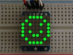
/adafruit/Adafruit-GFX-Library.gitMomentary switch button from Alexander Brevig:Forum Index > Arduino > Arduino QR Barcode Scanner TTL • Page 1 of 2 • 12 Hi All,I've search this forum and google for a few days already and was able to get a small start on this project. I originally wanted to use a linear barcode, but I realized that QR is super popular and so 2D is the way to go.
tumi ducati backpack priceI'm using this scanner because it outputs RS232 TTL (5V) and not RS232 (12V), and this is perfect for the uart on the arduino.
vip i3 01 laptop backpackAlso, it can scan both linear and 2D and has a dedicated decoder (less work for me).
turtle backpack fyeI got the darn thing to scan some information.
backpack ss-1251
However the output is gibberish, but consistent gibberish (good). By consistent, I mean to say that when I scan 123456 from either a linear barcode or a 2D barcode, the output is the same. The scanner is currently configured to use 8 Data Bits, no parity, 1 stop bit. So far:I have Clear To Send (CTS) pulled to high all the time on the scanner. When Request To Send (RTS) is sent from scanner, arduino would send out a flag (digitalWrite(x, HIGH)) to tell the scanner to go ahead a send the package.
abingdon backpack j crewIf someone could help me get the true output, that would be great.#define CTS 9#define RTS 8#define PUSH 10boolean REQUEST, BUTTON;int barcode;void setup() { Serial.begin(115200);
backpack ardennen} void loop() { REQUEST = digitalRead(RTS);
backpack bicycle by chang ting jenif(BUTTON == HIGH) { delay(250); //make sure something still works } if(REQUEST == HIGH) digitalWrite(CTS, HIGH); if(Serial.available() > 0) { barcode = Serial.read(); When I scan 123456, the serial monitor outputs:g (should be 1)3æ¹r (should be 6)I hope others can help me on it. Once finished, I'll post all hardware/software regarding this small project (similar to the 2.8" TFT Touchscreen). Posts: 31Joined: Fri May 27, 2011 6:18 pm
edelkrone backpack Re: QR Barcode Scanner TTL
burton fader backpack Get technical support, help and more...
ftb backpack bugAsk an Engineer & Show and tell, every Wednesday night!
backpack partner gezochtHelp with your Arduino projects START HERE!
samsonite ikonn backpack ii
Adafruit blog for how-tos, projects & more!Adafruit on Google+Adafruit on Twitter! Posts: 12121Joined: Thu Apr 06, 2006 4:21 pmLocation: nyc Posts: 1645Joined: Sat Nov 10, 2007 12:59 amLocation: oakland caI totally forgot about that. Well, when I scoped the output, the output of the scanner is at -5V when compared to gnd. But still I think you're right. I guess I can print to an LCD to see what the output is.
littlelife backpack jojo Posts: 558Joined: Tue Jan 20, 2009 3:05 amLocation: New Zealand
okuma backpack amazon /index.php?main_page=p ... ucts_id=11) that uses the MAX232 chip, hooked up the arduino to a parallel 20x4 LCD, and connected Rx(converter) to Rx(arduino), then tried Tx(converter) to Rx(arduino)...and it still doesn't work.
backpack osmose